Picking an Interface for a 0.49-Inch 1080p Micro OLED Near-Eye Module: MIPI DSI, LVDS, RGB or SPI
For a 0.49-inch 1920x1080 Micro OLED panel, the interface choice is settled long before the schematic is finished, and it constrains almost everything that follows: connector height, flex stiffness, board stack-up, firmware bring-up time and the power state machine. MIPI DSI is the natural fit here, because it moves a full high-definition stream over a small number of differential pairs instead of dozens of single-ended lines, and a near-eye product has no room to spare in the temple arm. SPI, MCU-8080 and parallel RGB remain sensible answers for small panels with far fewer pixels, and LVDS is still workable when the host already carries a proven LVDS transmitter. The trade-offs are not about raw speed alone; they are about what each bus does to your cable, your EMI profile and your first-week debug schedule.
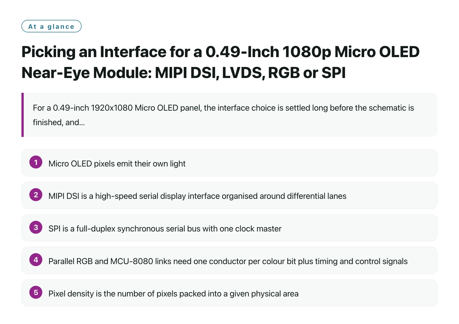
Key takeaways
- Micro OLED pixels emit their own light, so the module has no backlight assembly to route around, which pushes the mechanical and electrical budget straight into the flex, the connector and the optical stack.
- MIPI DSI is a high-speed serial display interface organised around differential lanes, so a 1920x1080 stream at 90 Hz travels on a few pairs rather than a wide parallel bus. [1]
- SPI is a full-duplex synchronous serial bus with one clock master, which makes it trivial to bring up but slow once the pixel count rises, so it does not scale to a 1080p panel at 90 Hz. [2]
- Parallel RGB and MCU-8080 links need one conductor per colour bit plus timing and control signals, which is manageable on a 320x240 module and painful inside a glasses frame.
- Pixel density is the number of pixels packed into a given physical area, and a small panel carrying 1920x1080 pixels sits in a very high density bracket where interface jitter, tearing and uneven brightness are visible to the wearer. [3]
A 0.49-inch diagonal with 1920x1080 pixels is a near-eye part, not a handheld part. The panel is specified at 1800 nits with a 50,000:1 contrast ratio, a 90 Hz refresh rate and a MIPI interface, and that combination only makes sense when the image is projected or viewed through optics a few centimetres from the eye. In that geometry the display is one element of a stack, and the cable feeding it is the element most likely to decide whether the product fits the frame you designed.
Interface choice is therefore a mechanical decision as much as an electrical one. A parallel RGB link at 24 bits per pixel needs a wide flex with many ground returns, a larger connector and a stiffer assembly that resists folding into a hinge. A serial link uses fewer conductors but demands controlled impedance, matched pair lengths and a receiver that can recover a fast clock, which moves the difficulty from the connector into the layout and the bring-up process.
This article compares the realistic options for this class of module, explains where each one breaks down in a wearable near-eye design, and gives a bring-up sequence that isolates power, link training, panel initialisation and image content in that order. It also covers the failure modes that show up after the first prototype works on the bench but not in the product. The assumption throughout is that the host is a small applications processor or a microcontroller with a display peripheral, and that no FPGA is available to improvise a custom timing generator. If you do have an FPGA, some of the constraints relax, but the optical and thermal ones never do.
Fix the frame budget before you fix the pin count
The first number to settle is the sustained pixel rate, because it decides which interfaces are even eligible. A 1920x1080 panel refreshed at 90 Hz needs just over two million pixels delivered every 11 milliseconds, and that requirement does not change when you change buses; only the cost of meeting it does. Blanking intervals, command traffic and any pause for a mode change all come out of the same budget, so a link that looks comfortable on paper at full rate can still starve if the host interleaves other traffic badly.
SPI at a few tens of megahertz cannot carry that payload. Even at generous clock rates, a serial pixel stream spends so many clock edges per pixel that the achievable frame rate collapses, and the CPU or DMA engine is pinned servicing the panel. That is why SPI is the right answer for a small 0.39-inch or 0.23-inch module with far fewer pixels and the wrong answer here. The same arithmetic rules out MCU-8080 and narrow parallel RGB links for a 1080p panel: the bus width simply cannot deliver the pixels in time.
What remains is a differential serial link. MIPI DSI is designed for exactly this job, moving display data, commands and control packets over one or more clocked lanes, with a low-power mode that lets the link idle between frames instead of burning power on a continuous high-speed stream. For a battery-powered wearable that low-power behaviour matters as much as the headline throughput, because the panel link is active whenever the product is on the wearer's head.
Pixel density is the concept that explains why this panel is unforgiving. [3] When thousands of pixels share a few square centimetres, every pixel is a large fraction of the visible field, so a single dropped frame or a badly timed mode switch is not a subtle artefact. It reads as a flicker or a tear right in the middle of the user's view.
If your host cannot sustain the pixel rate with margin for command traffic, stop optimising the connector and choose a different host or a different panel; no amount of careful layout fixes an underpowered transmitter.
The five interfaces you will realistically be offered
| Interface | How it moves pixels | Cost to the wearable design | Fit for a 0.49-inch 1080p Micro OLED |
|---|---|---|---|
| SPI | One clocked serial bit stream from a single master | Two to four wires and no length matching, but very low throughput | Practical for small low-resolution modules; too slow for 1920x1080 at 90 Hz |
| MCU-8080 style parallel | Byte-wide writes stroked by read/write and address lines | Roughly a dozen conductors, wide flex, more ground returns | Only viable at low resolution or for partial-update content |
| Parallel RGB | Continuous stream with one line per colour bit plus syncs | Wide high-pin-count connector, stiff cable, careful skew control | Feasible for the pixel count but hostile to a thin temple arm |
| LVDS | Low-voltage differential pairs carrying serialised pixel data | Several differential pairs with controlled impedance and matched lengths | Workable when the host already has an LVDS transmitter and the wiring has room. [4] |
| MIPI DSI | High-speed differential lanes carrying packets and pixel streams | Small conductor count with strict impedance, length and EMI rules | The intended interface for this module: 1080p at 90 Hz on a minimal harness |
What MIPI DSI bring-up actually involves
A serial display link has more states than a parallel bus, and most first-prototype problems come from skipping one of them. The host has to release the panel supply in the right order, wait for the panel's own power-on timing, start the clock lane, move the data lanes into high-speed mode, deliver an initialisation table, and only then push the first frame. Get the order wrong and the panel stays black with no error reported anywhere.
Parts such as the 0.49" MIPI Micro OLED display module from 0.49" MIPI Micro OLED display module are representative of the class: a 1920x1080 emissive panel whose only pixel path is the serial link, with no parallel fallback to fall back to when the link will not train. That makes a staged bring-up strategy mandatory rather than a nice habit.
Power sequencing and the initialisation table
Treat the panel as a device with its own boot state. The supply rails have to come up in a defined order, and the reset and enable lines have to be held for the minimum times stated in the panel documentation, not for whatever feels long enough. If the host starts sending packets while the panel is still settling, the packets are discarded silently and you will be debugging the wrong layer for a day.
The initialisation table is the second trap. Vendor tables are often written for a reference board with a specific supply and a specific lane count, so a table copied wholesale into a design with different rails or a different lane configuration can leave the panel in an almost-working state: backlight-less pixels flicker dimly, or the image appears only after a temperature change. Keep the table in version control as data, log every write, and be able to replay it over a debug interface.
Timing, tearing and the 90 Hz frame
At 90 Hz the panel receives a new frame every 11 milliseconds, which is short enough that tearing becomes visible during head motion. Tearing happens when the host updates the frame buffer while the panel is scanning it, so the fix is normally a double-buffered or command-mode scheme with an explicit frame boundary rather than a free-running stream. Decide this before you write the graphics layer, because retrofitting synchronisation into a renderer that assumes immediate presentation is expensive.
Also check the timing parameters you were given rather than the ones you assumed. Porches, sync widths and the front and back blanking intervals are part of the panel specification, and a link that trains successfully can still produce a shifted or rolling image if they are wrong. A test pattern of vertical bars at the native resolution makes timing errors obvious within seconds, whereas a photograph of a real scene can hide them.
EMI, the flex and the hinge
Differential links are more forgiving than parallel buses about the number of wires, but they are less forgiving about geometry. Two pairs routed over different lengths, or split around a connector pin field, will show up as intermittent link errors that depend on cable position. In a wearable the cable moves, so an intermittent fault can look like a firmware bug that only appears when the wearer turns their head.
Keep the pairs short, keep them over a continuous reference plane, and avoid running them beside the switching supplies that power the panel. If the link must cross a hinge or a sliding joint, budget for a shielded flex and for the extra thickness that shielding adds. This is the point where an interface decision turns into a mechanical one, and it is much cheaper to discover during the first mock-up than during tooling review.
The rule of thumb is that a serial link converts wiring problems into layout problems, and layout problems are cheaper to catch before the flex is ordered.
A bring-up order that isolates one layer at a time
- Verify every rail before connecting the panel. Measure each supply against its stated tolerance and check the sequencing order with a scope, not with a multimeter that averages away the order of events.
- Confirm the clock lane starts. Probe or read back a link status register to prove the host is transmitting a clock the receiver recognises before you worry about pixels.
- Send the initialisation table and read something back. A register read that returns the value you wrote proves the command path works; it separates a dead link from a wrong parameter set.
- Display a native-resolution test pattern. Vertical bars or a checkerboard expose timing, offset and lane-swap errors that a photograph of a UI mock-up will hide completely.
- Repeat the whole sequence at temperature extremes and at the lowest supported battery voltage. Link margin and panel timing both shrink at the corners, and a prototype that trains reliably on a bench supply may fail on a partly discharged cell.
Keep a bare panel and a known-good reference board on the bench throughout development. When a product build shows a blank screen, swapping the panel into the reference board answers in one minute whether the fault is in the panel, the cable or the host. Without that baseline, every display bug turns into an argument between teams about whose layer is broken.
Decision criteria that survive contact with production
Once the interface is chosen, the selection work is not finished; it moves to the details that only matter at volume. Ask for the panel's power sequencing requirements, the initialisation table as machine-readable data, the lane configuration the module was characterised with, and the recommended flex stack-up and impedance. A supplier who can hand over the timing table and a reference layout shortens bring-up by weeks; one who cannot is a schedule risk that no price advantage offsets.
Budget the connector and cable as first-class parts. On a near-eye product the display harness is often the most expensive and most delicate interconnect in the system, and it is the part most likely to be replaced late in the programme. Choosing a smaller conductor count early gives you room to add shielding or strain relief later without redesigning the whole assembly.
Finally, plan for the thermal path. An emissive panel that is bright enough for daytime near-eye use is dissipating power close to the wearer's face, and the enclosure must be able to move that heat away without the skin temperature becoming uncomfortable. The panel interface does not set the thermal budget, but the power state machine around it does, so low-power link modes and aggressive frame-rate reduction when nothing is changing are engineering features, not power-saving trivia.
Shortlist two interface options while the optics are still fluid, then lock the one whose mechanical consequences you can live with for the whole product life.
Sources
Frequently asked questions
Why is MIPI DSI preferred over parallel RGB for a 0.49-inch 1920x1080 Micro OLED module?
A parallel RGB link needs one conductor per colour bit plus clock, sync and control lines, which means a wide connector and a stiff cable that is hard to route into a thin temple arm. MIPI DSI carries the same pixel stream over a few differential lanes, so the harness is thinner and lighter. The trade-off is stricter impedance, length matching and EMI discipline in the layout, plus a longer software bring-up path.
Can I drive this panel over SPI if I only need a low frame rate?
You can drive small Micro OLED panels over SPI, but the pixel budget of 1920x1080 makes it impractical: the serial clock edges needed per frame push the achievable refresh rate far below what a near-eye product needs to avoid visible flicker. SPI also consumes host CPU or DMA bandwidth continuously. Use SPI for small low-resolution modules and reserve a differential serial link for high-resolution panels like this one.
What causes a blank screen on a MIPI DSI panel that trained successfully?
The most common causes are a missing or truncated initialisation table, an incorrect supply sequencing order, and a display stream that starts before the panel has finished its own power-on timing. Lane swaps and wrong timing parameters usually produce a distorted image rather than a blank one, so a black panel points at the command path first. Reading back a written register is the quickest way to separate a dead link from a wrong parameter set.
How do I choose between an integrated MIPI interface and adding a bridge chip?
A bridge chip adds a component, a power rail and a second configuration surface, but it can connect the panel to a host that only offers parallel RGB or LVDS. Choose the bridge only when the host choice is fixed and cannot be changed, and then budget board area and bring-up time for the extra link. If the host already has a MIPI DSI display peripheral, the integrated path is simpler and removes a failure point from the assembly.
What should I ask a supplier before committing to tooling for a near-eye module?
Ask for the power sequencing requirements, the initialisation table in machine-readable form, the lane configuration and flex stack-up the module was characterised with, and separate drawings for the visible area and the connector keep-out. Those items determine whether the first worn prototype works without a mechanical change. Also confirm how low-power link modes behave, because idle power decides battery life in a product that is worn all day.